Dental CoCr SLM Printing

Cobalt chromium (CoCr) alloy is widely used in the manufacturing of dental restorations such as partial denture supports, crowns, and bridges due to its excellent biocompatibility, wear resistance, and corrosion resistance. Selective Laser Melting (SLM) technology is currently the mainstream process for dental CoCr alloy printing.

The complete dental CoCr printing process consists of three stages: pre preparation (powder processing and equipment matching), printing core (SLM molding), and post-processing (cutting and separation, heat treatment, surface finishing). This set of equipment covers all the above links, involving a total of 12 types of equipment.
Request a quote

Device Relationship

Equipment system architecture

The following shows the connections and material flow relationships between 12 types of devices. The equipment is divided into four subsystems according to their functions: supporting facilities, pre-processing, printing core, and post-processing technology.

SubsystemEquipment CompositionFunctional Description
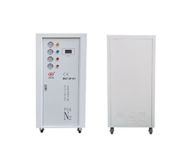
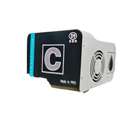
Supporting FacilitiesPower stabilizer, water cooler, nitrogen generator, refrigerated dryerProvide stable power, cooling cycle, and protective atmosphere for the printing core
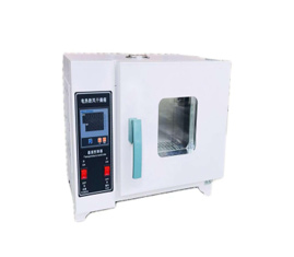
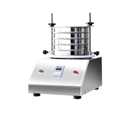
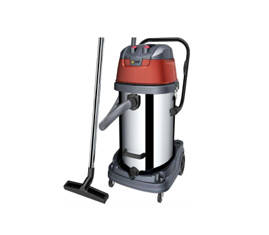
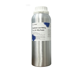
PreprocessingDrying oven, screening machine, vacuum cleaner, metal powderPowder drying, grading, and recycling to ensure printing quality and safety
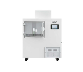
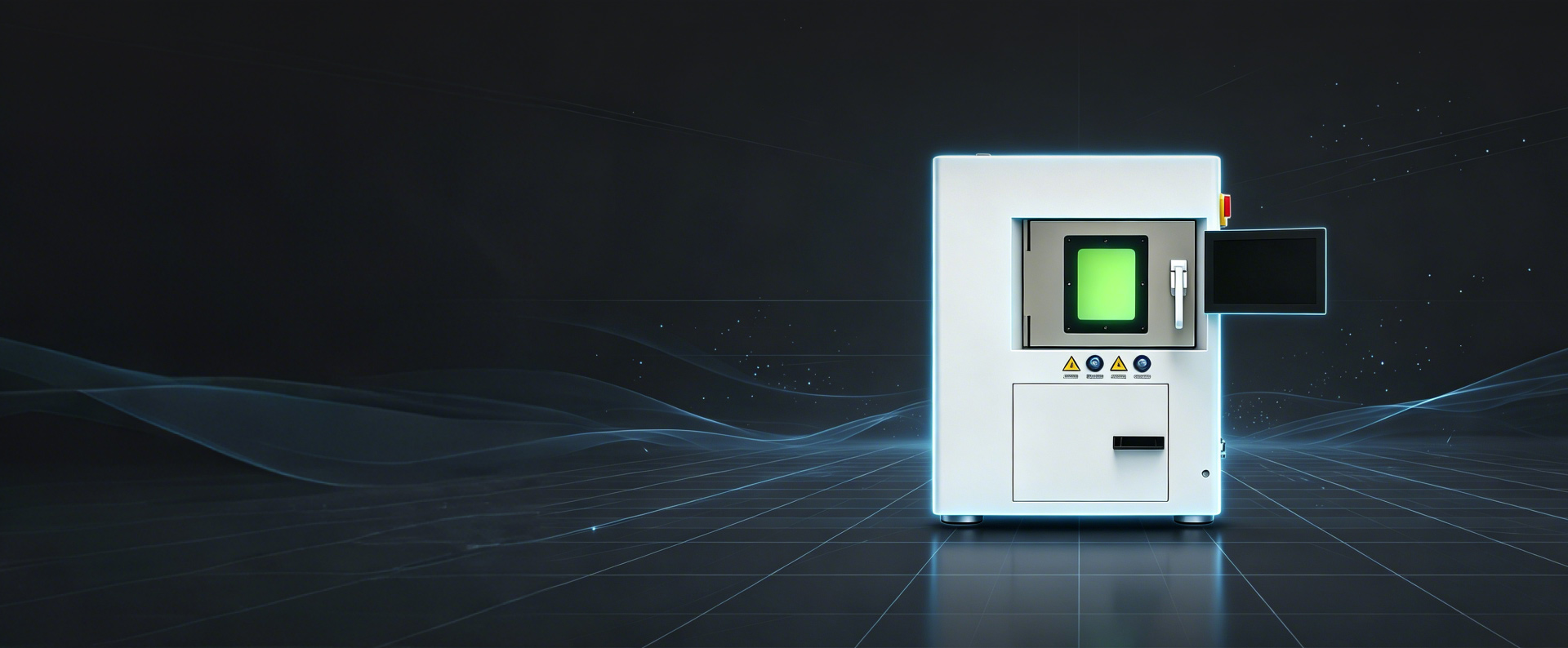
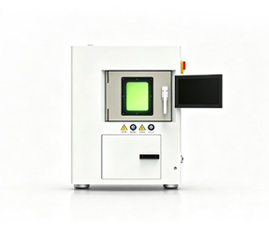
Print CoreMetal Printer (SLM)Selective laser melting forming of CoCr alloy powder
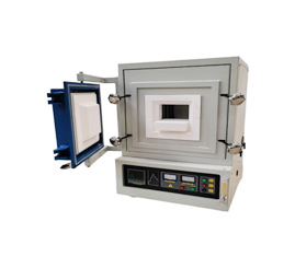
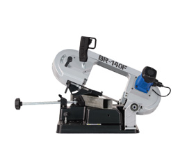
Post-ProcessingTable saw, heat treatment furnace, polishing machineSubstrate separation, stress relief annealing, surface finishing


Device interconnection relationship

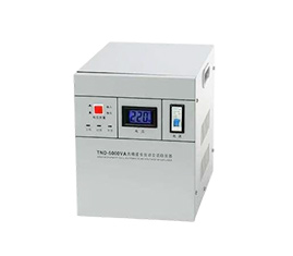
Power Supply RelationshipPower stabilizer → metal printer (providing stable 220V power supply to prevent voltage fluctuations from damaging the laser system)
Cooling RelationshipWater cooling machine → metal printer (circulating cooling water takes away the heat from the laser source to ensure beam stability)
Gas Supply RelationshipNitrogen generator+refrigerated dryer → metal printer (the nitrogen generator produces high-purity nitrogen gas, the refrigerated dryer dries compressed air, and the two work together to inject dry nitrogen gas into the printing chamber to isolate oxygen and prevent oxidation of molten metal)


After printing is completed, the parts are taken out of the printing chamber along with the substrate and enter the post-processing stage:


Powder management closed-loop:

Device Details

Complete Process Flowchart

Standard Operating Procedure

The following is the complete operation process of dental CoCr alloy printing (arranged in chronological order):

StepsEquipmentStageOperation Content
01Drying OvenPreparatory workPut CoCr powder into a drying oven for drying and dehumidification
02Screening MachinePreparatory workSieve to ensure uniform powder particle size
03Nitrogen Generator+Refrigerated DryerDevice startupStart the nitrogen production and cold drying system, pre charge the printing
chamber with nitrogen gas
04Power Stabilizer+Water CoolerDevice startupTurn on the stabilizing power supply and start the circulation of the chiller
05Metal PrinterPrint CoreLoad powder → Import model → SLM printing forming
06Vacuum CleanerPrint completedClean up residual powder in the printing compartment
07Table Sawpost-processingCut and separate the parts from the substrate
08Heat Treatment Furnacepost-processingHigh temperature annealing to relieve stress
09Polishing Machinepost-processingSurface precision machining to mirror level smoothness
10Screening Machine+Drying OvenPowder recyclingRecycled powder sieving+drying, recycling


Powder Material Circulation Path

The utilization rate of CoCr metal powder in SLM printing is usually between 50-80% (depending on the geometric complexity of the part and the support structure). Unmelted residual powder can be recycled and reused. The complete powder circulation path is as follows:

 lc_03.jpg


Equipment Layout Suggestions

Based on the connection relationship between devices, the following physical layout is recommended:

Printing Core AreaThe metal printer is placed in the center, with the power regulator and chiller placed adjacent to the printer (with the shortest connection)
Gas Supply AreaThe nitrogen generator and refrigerated dryer can be placed on one side of the printer to deliver dry nitrogen gas to the printing chamber through pipelines
Powder Processing AreaThe drying oven, screening machine, and vacuum cleaner are centrally placed for easy access and recycling of powder
Post-Processing AreaThe table saw, heat treatment furnace, and polishing machine are arranged in sequence to form a production line operation

This website uses cookies to enhance the user experience. By clicking 'Accept', you agree to our use of cookies.